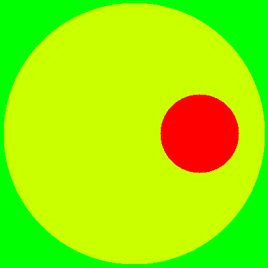
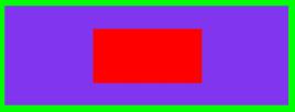
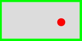
100 30 25 1.0006 off-centre2.bmpThis is used for producing bitmaps of a circular conductor inside another circular conductor. In this example, the inner diameter of the outer conductor is 100 mm, the outer diameter of inner conductor is 30 mm. The inner is offset 25 mm from the centre. The dielectric constant of the material between the inner and outer is 1.0006 (air). The fact the outer looks square, not circular, is of no consequence. The shape inside of the outer conductor is round - the shape outside is irrelevant..

268 100 100 50 4.8 central.bmp This is used for creating bitmaps of a rectangular conductor placed centrally inside another rectangular conductor. Only a single dielectric exists.

This is used for the generation of bitmap with a circular conductor inside a rectangular conductor.

create_bmp_for_rect_in_circ has not been finished yet.But this is what it will do - calculate the properties of a transmission line formed from a circular outer and a rectangular inner.

create_bmp_for_stripline_coupler -v 2.0 1.01 1.02 1.0 coupler.bmpThis is used for creating bitmaps for a directional coupler. In this example, the height H of the enclosure is 2 mm, the width of the conductors w is 1.01 mm, the spacing between them is 1.02 m. The dielectric between them has a permittivity of 1.0. The width of the enclosure W is automatically set, to be sufficiently large to make no significant difference to the results. The inner conductors are made only one pixel high, so that the bitmap produced closely approximates a geometry that has an exact analytical solution, which the -v option causes the program to compute (Zodd=93.196255, Zeven=106.612606 and Zo=99.678963 Ohms). The thickness of the inner conductors is shown exaggerated here, otherwise you would be unable to see them. You will really need to zoom in with a graphics package to see the inner conductors.
 .
.create_bmp_for_symmetrical_stripline 1 201 301 wide.bmpThis is used for creating bitmaps of a thin strip line between two wide conductors. The program also calculates the theoretical impedance, assuming the stripline is infinitely thin and the width W infinite wide. The inner conductor that is produced is one pixel high, in order that
atlc may be tested against theoretical data. It is often difficult to see the inner conductor unless you zoom into a bitmap. Hence it is shown very exaggerated in this diagramme.  .
.268 100 10 40 25 200 100 45 1.0 4.8 pcb2.bmpThis is used for creating bitmaps for a rectangular conductor placed anywhere inside another rectangular conductor, with one conductor place on top of another dielectric. The programme create_bmp_for_rect_in_rect is quite hard to use, as it has so many parameters that must be supplied. Don't try using this one before some of the others.

create_bmp_for_microstrip_coupler 2.5 2.0 1 1.593 0.53 1 3.7This is used when one wishes to create bitmaps for two coupled lines microstrip lines on a PCB. In this example, the width of the coupled lines (w) is 2.5 mm, there is a 2 mm space (s) between the two coupled lines, there is a gap (g) of 1 mm between the edges of the coupled lines and the top groundplane. The dielectric is 1.593 mm thick and the copper tracks 0.53 mm thick. The permittivity of the material (air) above the PCB is 1.0 and that of the PCB is 3.7. This has an odd mode impedance of 43.96 Ohms and an even mode impedance of 55.06 Ohms. .
